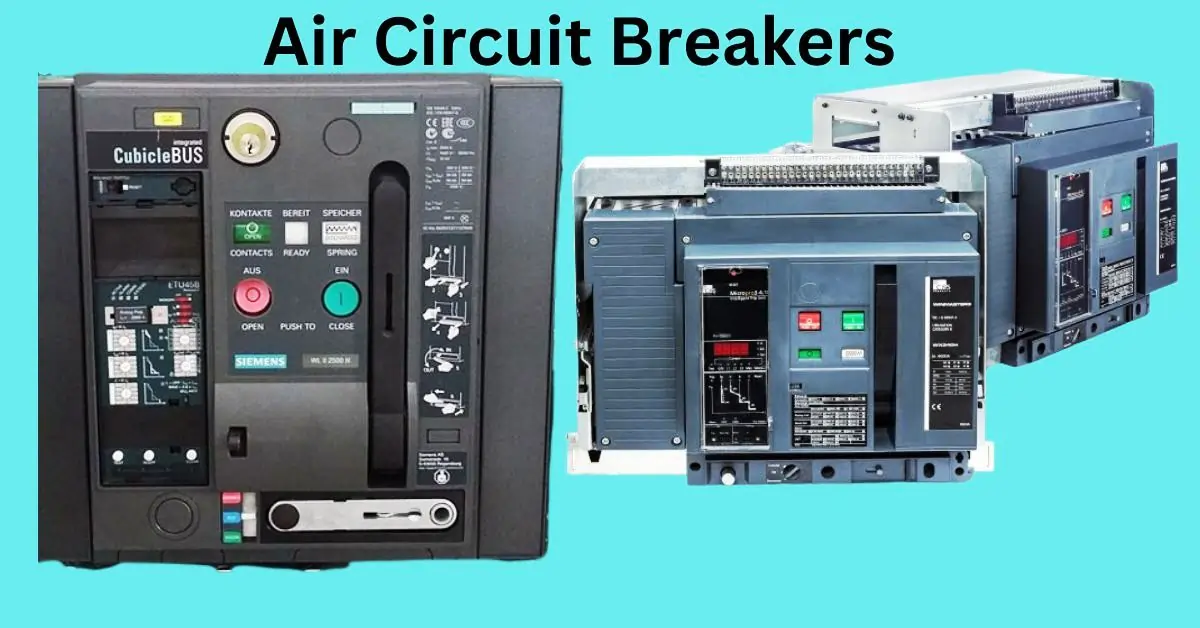
How Air Circuit Breaker Works
Circuit breakers are crucial for maintaining safety and operational reliability in electrical systems, especially in marine applications. Onboard ships and vessels, electrical systems are exposed to harsh environments and demanding conditions, making protection against faults like overloads and short circuits essential. The Air Circuit Breaker (ACB) is a vital component in managing and safeguarding electrical circuits in marine settings.
Designed to interrupt large currents, the ACB helps protect critical equipment and ensure continuous power supply, even in challenging marine conditions. In this article, we’ll explain how the Air Circuit Breaker works in marine applications, exploring its fundamental principles and functionality. We’ll also highlight five key insights into its operation, emphasizing its importance in protecting both the vessel’s electrical infrastructure and its crew. By the end, you’ll understand why ACBs are indispensable for maintaining electrical safety and reliability in marine environments.
What is an Air Circuit Breaker?
Definition and Full Form of ACB
An Air Circuit Breaker (ACB) is a type of electrical circuit breaker that uses air as the medium for interrupting electrical faults. It is designed to protect electrical circuits from damage due to overloads, short circuits, and other electrical faults by automatically disconnecting the faulty circuit.
Role as a Mechanical Switching Device
The ACB functions as a mechanical switching device that can make, carry, and break the flow of electrical current. It is capable of handling both normal and abnormal electrical conditions, ensuring the safety and stability of the circuit.
Handling Normal and Abnormal Circuit Conditions
ACBs are designed to operate under normal conditions by allowing the flow of electricity, but they also have the ability to interrupt the current during abnormal conditions like overloads or short circuits. They can:
- Make: Close the circuit and allow current to flow under normal conditions.
- Carry: Maintain the flow of current safely under normal operational loads.
- Break: Interrupt the current during faults such as overloads, short circuits, or under voltage conditions.
Key Uses of Air Circuit Breakers
ACBs are essential in protecting:
- Electrical Equipment: They safeguard generators, transformers, and other power equipment from damage caused by excess current.
- Distribution Lines: ACBs prevent faults from spreading across power distribution networks, maintaining system stability.
- Fault Protection: They protect circuits from faults like overloads, short circuits, and under voltages, ensuring the continuous, safe operation of electrical systems.
Working Principles of Air Circuit Breakers
Air Circuit Breakers (ACBs) are designed to protect electrical circuits by interrupting the current flow during abnormal conditions such as overloads or short circuits. The efficient operation of ACBs relies on a combination of advanced components and mechanisms that ensure the safety and reliability of the electrical system. Here’s a detailed look at how ACBs operate in real-time to ensure safety and control:
Core Components and Design of ACBs
The ACB consists of several key components that work together to monitor, control, and interrupt the electrical current:
- Contacts: Responsible for opening and closing the circuit.
- Arc Interruption System: Manages the high-energy arcs generated during fault conditions.
- Trip Mechanism: Detects fault conditions and triggers the breaker to open.
- Operational Mechanism: Enables contact opening and closure.
These components are precisely designed to handle high currents and provide reliable protection against electrical faults.
a. Arc Interruption Mechanism
During a fault, such as a short circuit or overload, a high electrical current passes through the ACB, generating a high-energy electric arc between the contacts. The arc is dangerous because it can cause severe damage to the breaker and surrounding equipment if not handled properly.
ACBs contain and extinguish the arc by quickly separating the contacts, utilizing air as the arc-quenching medium. The arc is rapidly cooled and extinguished through a series of techniques, ensuring the current flow is interrupted safely and without lasting damage.
b. Contact Structure and Material
The contact materials used in ACBs are often made of arc-resistant metals such as copper or silver alloys. These materials are designed to withstand high temperatures and the intense energy released during an arc event.
The contact separation speed is critical in reducing the arc duration. ACBs are designed for rapid contact separation to minimize the time the arc can persist. The faster the contacts separate, the quicker the arc is extinguished, thus ensuring the circuit is interrupted promptly and safely.
c. Air Blast Mechanism
One of the most important features of ACBs is the air blast mechanism, where pressurized air is used to cool and extinguish the arc once the contacts are separated.
When the contacts open, pressurized air is directed across the arc, helping to cool the plasma and extinguish the arc much faster than relying on natural air circulation alone. This rapid cooling prevents further damage to the breaker and allows it to reset quickly for the next operation.
The air blast mechanism significantly improves the speed and effectiveness of arc quenching, ensuring that the ACB can respond swiftly to faults.
d. Operating Mechanism and Trip Settings
The operating mechanism of an ACB detects fault conditions, such as overloads, short circuits, or under-voltage, and triggers the breaker to open the contacts. This process is controlled by a series of trip units that sense abnormalities in the current or voltage.
ACBs have adjustable trip settings that determine how the breaker responds to different fault conditions. These settings include overload protection, short circuit protection, and time-delay functions. The trip unit ensures that the ACB only opens when necessary, providing reliable protection without unnecessary interruptions.
e. Safety and Reset Functions
ACBs are designed to enhance system safety by preventing circuit damage during faults and ensuring a quick reset after the interruption. Modern ACBs often feature self-resetting mechanisms or manual reset buttons to restore the system after the breaker has operated.
This reset function is essential for minimizing downtime in electrical systems, particularly in industrial or marine applications where continuous power is critical. Additionally, ACBs are equipped with safety interlocks that prevent accidental or premature closing, further protecting equipment and personnel.
These advancements in ACB design and functionality have made them indispensable for ensuring reliable operation and safety in complex electrical systems.
Understanding the Air Circuit Diagram
Introduction to Air Circuit Diagrams
Air circuit diagrams are vital for comprehending the operation and functionality of air circuit breakers. These diagrams visually represent the electrical and mechanical components, showcasing their interactions during normal operation and fault conditions. By analyzing these diagrams, engineers and technicians can better understand the breaker’s design, troubleshoot problems efficiently, and ensure proper maintenance and reliable operation.
The Value of Air Circuit Diagrams for Comprehending Breaker Function
Air circuit diagrams are crucial for several reasons:
- Operational Clarity: These diagrams outline the sequence of operations, from contact closure to arc extinguishment, ensuring a clear understanding of the breaker’s functionality.
- Troubleshooting: Technicians can use the diagrams to trace electrical flow, pinpoint potential failures, and streamline diagnostics and repairs.
- Maintenance: A detailed component layout aids in routine inspections and maintenance, enhancing efficiency.
- Safety: By providing a comprehensive view of the breaker’s design and operation, the diagrams help technicians work safely on or around the equipment.
Overview of Symbols and Components Commonly Used
Overview of Symbols and Components in Air Circuit Diagrams
Air circuit diagrams employ standardized symbols to depict components and their functions, including:
- Contacts: Represented by parallel lines that indicate open or closed states.
- Arc Chutes: Shown as segmented blocks where electrical arcs are extinguished.
- Coils and Magnetic Elements: Illustrated as loops or spirals, representing magnetic fields and blowout coils.
- Current Paths: Depicted as lines that trace the flow of current through the breaker.
Key Components in Air Circuit Diagrams
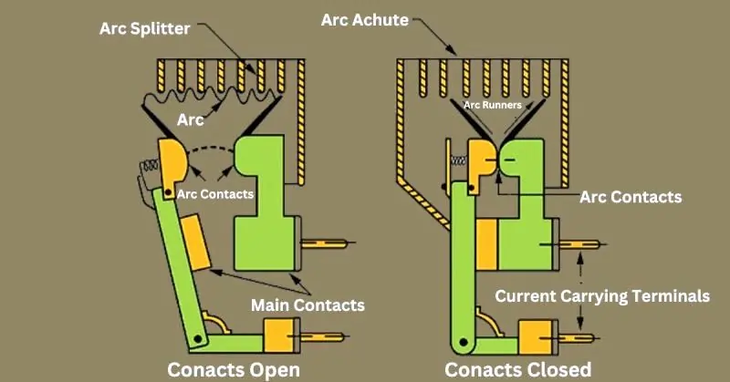
Arc Runners: Guided lines that direct the arc towards the arc chute for safe extinction.
Contact Open: Indicates an interrupted circuit with no current flow, shown as separated lines in the diagram.
Main Contacts: Primary load-carrying contacts during normal operation, represented by parallel lines that connect or disconnect the circuit.
Arc Contacts: Specialized contacts that manage the arc during high-current interruptions, engaging first and disengaging last.
Arc: Depicted as a zigzag or lightning bolt, representing the plasma discharge when current is interrupted.
Arc Splitter: Shown as a series of parallel lines or plates, these devices divide and extinguish the arc effectively.
Contact Closed: Represents a completed circuit allowing uninterrupted current flow, illustrated by connected lines.
Current-Carrying Terminals: Points of entry and exit for current within the breaker, marked with terminal connection symbols.
Interpreting Air Circuit Diagrams
Step-by-Step Guide
- Identify the Power Source:
Locate the input and output terminals where power enters and exits the breaker. - Trace the Current Path:
Follow the lines from the power source through the main contacts and arc contacts to understand the current flow. - Understand Contact States:
Differentiate between open and closed positions of contacts, noting when the circuit is complete or interrupted. - Locate Arc Handling Components:
Identify key elements like arc contacts, arc runners, and the arc chute, and understand their roles in managing and extinguishing arcs. - Examine the Trip Mechanism:
Study how the trip unit operates to open the contacts during fault conditions, ensuring safe operation.
Example Diagrams with Explanations
- Diagram Overview:
A basic diagram showing labeled components:- Main Contacts: Represent load-carrying parts.
- Arc Contacts: Manage arcs during interruption.
- Arc Chute: Extinguishes arcs safely.
- Sequence Explanation:
- Normal Operation: Current flows smoothly through the main and arc contacts.
- Fault Condition: Arc contacts handle the arc, guided by runners to the arc chute for extinguishment.
Practical Tips for Engineers and Technicians
- Regular Review:
Familiarize yourself with the diagram frequently to enhance your ability to quickly identify components and their roles. - Use During Maintenance:
Always reference the diagram during inspections or repairs to locate components and understand their interactions. - Keep Diagrams Updated:
Ensure diagrams reflect the latest modifications or upgrades to maintain accuracy and reliability.
Because of their ability to manage high fault currents, ACBs are appropriate for demanding applications.
Comparison with Other Circuit Breaker Types
Air Circuit Breakers (ACBs) excel in specific scenarios due to their unique features. Here’s how they compare to other common circuit breakers:
Comparison with Miniature Circuit Breakers (MCBs)
- Current Capacity: ACBs handle significantly higher currents, making them ideal for industrial and commercial use.
- Applications: Low-current domestic environments are better suited for MCBs.
Comparison with Vacuum Circuit Breakers (VCBs)
- Arc Quenching Medium: VCBs use vacuum for superior arc suppression, especially in high-voltage systems, while ACBs rely on air.
- Economy: ACBs are more cost-effective and better suited for medium-voltage environments where fast response is needed.
Comparison with SF6 Circuit Breakers
- Performance: Sulfur hexafluoride gas is used by SF6 breakers to provide outstanding arc quenching in high-voltage situations.
- Cost-Effectiveness: ACBs are more economical and practical for medium- and lower-voltage applications, providing reliable protection at a lower cost.
ACBs strike a balance between performance and affordability, making them versatile for a wide range of applications.
Maintenance and Troubleshooting Tips for Air Circuit Breakers
Proper maintenance and timely troubleshooting are essential for ensuring the reliability and durability of Air Circuit Breakers (ACBs). Regular care minimizes the risk of unexpected failures and extends the breaker’s operational life. Below is a concise summary of key maintenance tasks and troubleshooting guidelines.
| Task | Description | Frequency |
|---|---|---|
| Regular Inspection | Inspect ACB for visible signs of wear, corrosion, or damage, especially on contacts and trip mechanisms. | Monthly or Quarterly |
| Contact Wear Check | Examine the contact surfaces for signs of wear or pitting, which can affect the breaker’s ability to interrupt current. | Annually |
| Arc Chute Inspection | Inspect the arc chute for cracks, dirt, or wear. A damaged chute can cause the arc to remain active longer, increasing wear. | Annually or After Major Faults |
| Clean the Breaker | Clean the ACB contacts, arc chute, and operating mechanisms to prevent dust and debris buildup, which can impair functionality. | Annually |
| Lubricate Moving Parts | Lubricate the moving parts, such as the trip mechanism and contact arms, to ensure smooth operation. | Annually |
| Test Trip Mechanism | Test the trip mechanism to ensure it responds promptly to faults. Check the trip unit settings and adjust as needed. | Semi-Annually |
| Check for Loose Connections | Tighten all electrical connections, including those on the breaker’s terminals, to prevent overheating or arcing. | Annually |
Basic Troubleshooting Steps
| Issue | Possible Cause | Troubleshooting Steps |
|---|---|---|
| Breaker Not Tripping During Fault | Fault in the trip unit or mechanism | – Test the trip unit and reset if necessary. |
| – Inspect and test the trip mechanism for proper function. | ||
| Excessive Wear on Contacts | Overload conditions or frequent fault tripping | – Inspect contacts for damage or erosion. |
| – Replace worn contacts if necessary. | ||
| Breaker Fails to Close Properly | Dirt or debris in the mechanism, worn springs | – Clean the breaker and lubricate moving parts. |
| – Replace any worn springs or faulty components. | ||
| Arc Chute Issues | Cracks or damage to the arc chute causing improper arc quenching | – Inspect and clean the arc chute. |
| – Replace damaged or worn arc chute components. |
Future Innovations in Air Circuit Breaker Technology
The demand for safer, more efficient, and intelligent electrical systems is driving rapid advancements in Air Circuit Breaker (ACB) technology. These innovations focus on improving functionality, enhancing safety, and leveraging modern monitoring techniques. Below are key trends and future developments shaping ACB technology.
Emerging Trends and Technological Advances in ACB Design
1. Smart ACBs with IoT Integration
The incorporation of IoT technology is transforming ACB functionality. Smart ACBs equipped with sensors and connectivity enable real-time remote monitoring, fault detection, and predictive maintenance. These systems allow operators to access performance metrics, addressing potential issues before they escalate.
2. Enhanced Arc Interruption Mechanisms
Future ACBs will utilize advanced arc interruption methods, such as improved air blast systems or hybrid vacuum and gas-based solutions. These innovations reduce arc duration, enhance current interruption capacity, and extend the breaker’s operational life.
3. Miniaturization and Space-Efficient Designs
As space becomes a premium in modern electrical systems, ACBs are evolving toward more compact designs without compromising performance. This miniaturization supports streamlined installations in industrial and commercial settings.
4. Improved Safety Features
Next-generation ACBs will integrate advanced safety mechanisms, such as real-time fault isolation, enhanced insulation materials, and self-diagnostic capabilities, ensuring safer operations in high-demand environments.
5. Integration with Renewable Energy Systems
ACBs of the future will be optimized for renewable energy applications, including solar and wind power systems. These breakers will support bi-directional power flow and adapt to fluctuating energy loads.
FAQ: How Air Circuit Breaker Works
Q. Which air is used in ACB?
Ans. ACBs operate using atmospheric air at normal pressure.
Q. What is the working principle of ACB and VCB?
Ans. ACBs use air to cool and stretch the arc, helping to extinguish it safely during faults.
Q. What is the working principle of a circuit breaker?
Ans. Circuit breakers interrupt current flow using an electromagnetic force that increases with larger currents.
Q. Which gas is used in ACB?
Ans. The common gas used in ACBs is sulfur hexafluoride (SF6) for arc quenching.
Conclusion
Air Circuit Breakers (ACBs) play a crucial role in modern electrical systems by providing reliable protection and ensuring the safe operation of power distribution networks. Through advanced arc quenching techniques and robust tripping mechanisms, ACBs effectively interrupt current flow during electrical disturbances, safeguarding equipment and preventing potential hazards. As technology continues to evolve, the role of ACBs will only become more vital, enhancing the safety, efficiency, and reliability of electrical infrastructures worldwide. Their continued development will help meet the growing demands of energy systems, ensuring that we can rely on safe and uninterrupted power for years to come.